

Where the heat goes, and what the air does about it
DraftSolver models air-cooled condensers, dry coolers, air-cooled heat exchangers and natural-draft towers from one setup and one set of correlations: a rating, a sweep, a design, an annual run, a transient, the ASME PTC 30.1 curves and acceptance test, and CFD of the same plant, each with a datasheet.
DraftSolver opens in 2027. Early access is granted by application.
What sets it apart
One workflow from the 1-D model to CFD. A plant is set up once, and the same case is rated, swept, designed, run through a weather year, simulated in time and tested to ASME PTC 30.1, then ported to CFD of the same plant and read back beside the rating, or solved together with it in a co-simulation.
- Crosswind in the 1-D modelCrosswind and plume recirculation are in the one-dimensional model, not left to CFD.
- Every number shows its workingA result names the equations that produced it, each opening its Handbook page with its source, its fitted range and its stated accuracy.
- A stated uncertaintyEvery rating carries its uncertainty band, broken down by the closure it comes from.
- A public validation recordIt lists 47 cases, each naming what it was compared with: a published calculation, a measurement or another model.
- Independent of the vendorAdiabat builds no cooling plant, so an owner can judge a vendor's guarantee on a model that is not the vendor's.
One setup, seven analyses
A case is set up once: the plant, its finned tube, the ambient and the models. Every analysis then runs on that setup. A rating, a sweep, a design and a year of hourly ratings of one plant therefore report the same quantities, and each run comes with a datasheet that lists the equations which produced it.
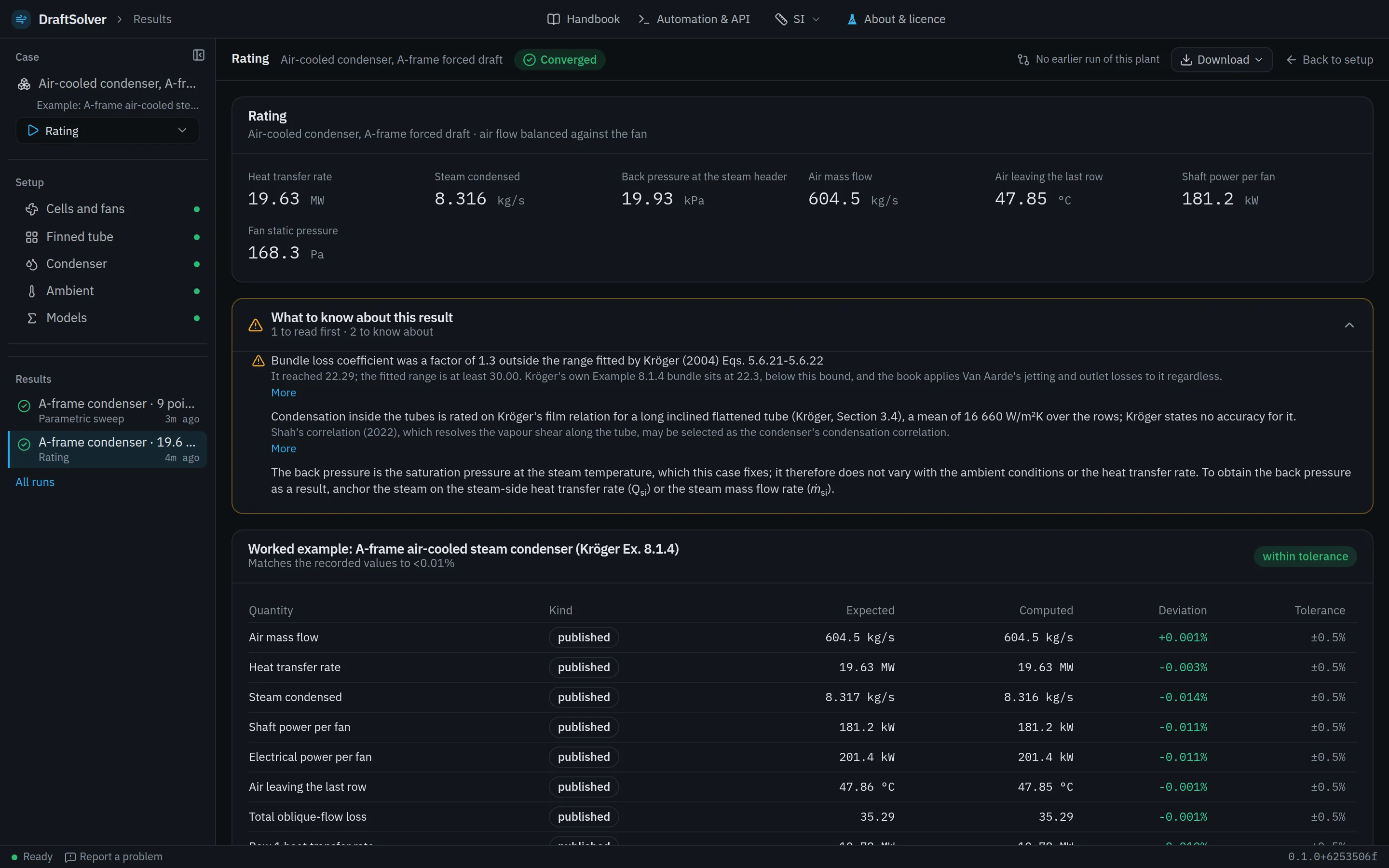
The system and the analysis. A case is saved as one file and opened again with its setup and its run settings.
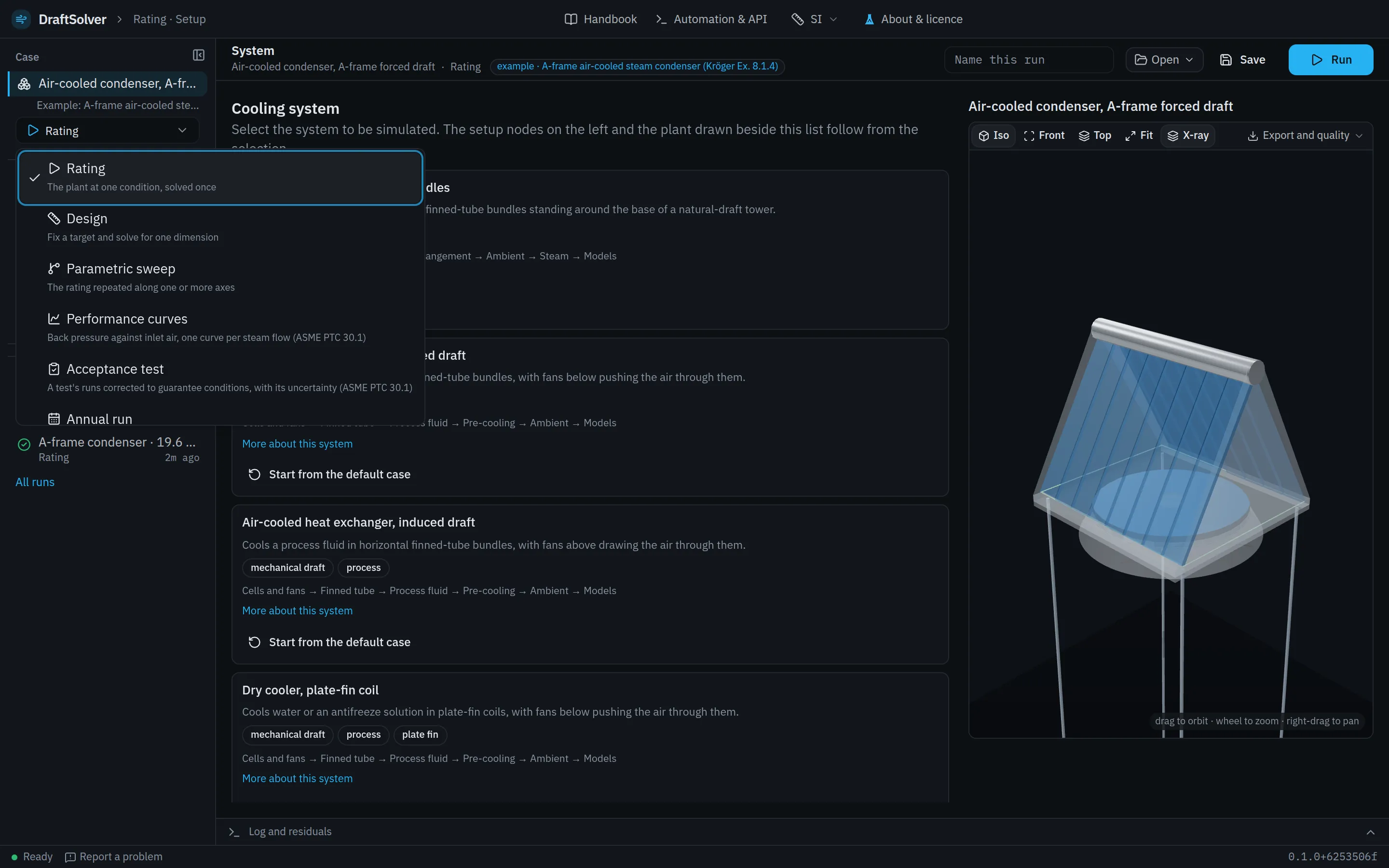
The plant node by node: the tower shell or the cells and fans, the finned tube, the bundles, the fluid, the ambient and the models. Each node shows whether its fields are valid before anything runs.
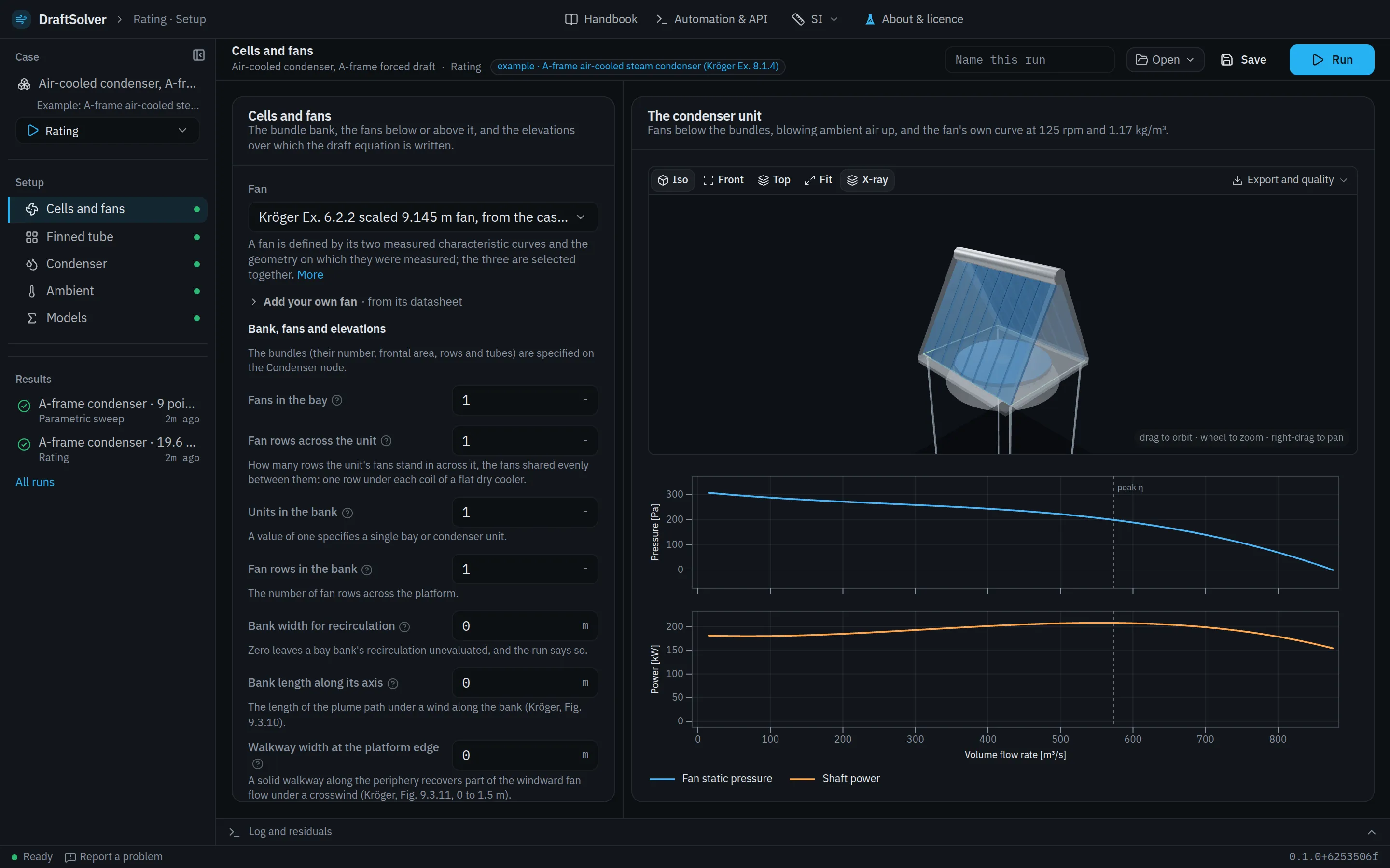
The analysis's own settings: a sweep's axes, a design target, a test's data, a year's weather, a transient's scenario.
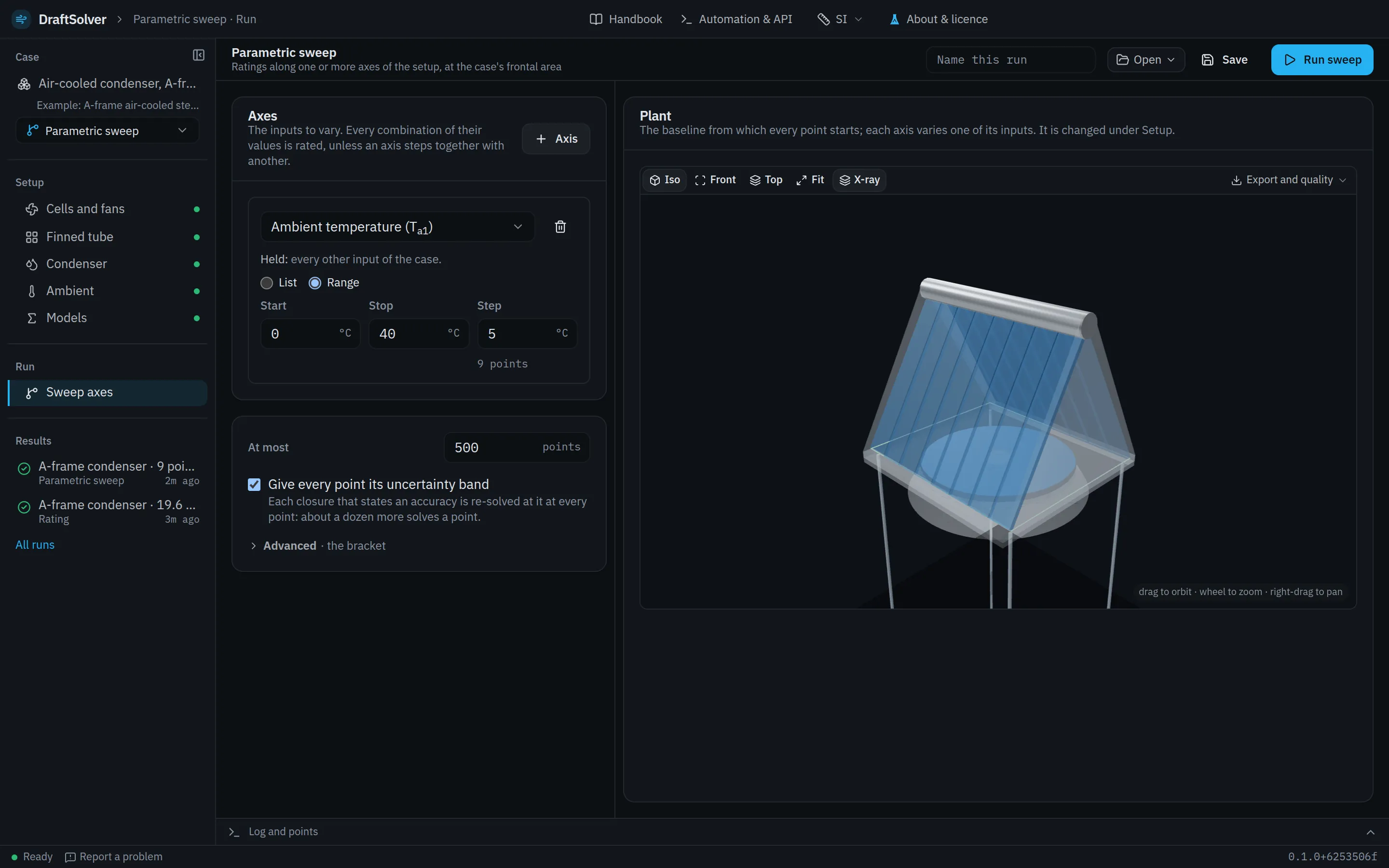
The plant's figures, the findings graded by how much they matter, the equations that produced the result, and the datasheet.
| System | Rating | Design | Parametric sweep | Performance curves | Acceptance test | Annual run | Transient simulation |
|---|---|---|---|---|---|---|---|
| Air-cooled condensers | |||||||
| Air-cooled condenser, A-frame forced draft | ● | ● | ● | ● | ● | ● | ● |
| Air-cooled condenser, A-frame induced draft | ● | ● | ● | ● | ● | ● | ● |
| Dry coolers | |||||||
| Dry cooler, plate-fin coil | ● | ● | ● | – | – | ● | ● |
| Dry cooler, plate-fin coil, induced draft | ● | ● | ● | – | – | ● | ● |
| Air-cooled heat exchangers | |||||||
| Air-cooled heat exchanger, forced draft | ● | ● | ● | – | – | ● | ● |
| Air-cooled heat exchanger, induced draft | ● | ● | ● | – | – | ● | ● |
| Natural-draft towers | |||||||
| Direct natural draft, vertical bundles | ● | ● | ● | – | – | ● | ● |
| Indirect dry cooling, natural draft, horizontal array | ● | ● | ● | – | – | ● | ● |
| Indirect dry cooling, natural draft, vertical bundles | ● | ● | ● | – | – | ● | ● |
Nine systems, from the condenser street to the tower
Each system is solved from its own draft equation, its loss coefficients and the heat transfer on the air side and the fluid side. Crosswind and recirculation enter the one-dimensional model wherever the literature states a method for them.
Air-cooled condensers
- Air-cooled condenser, A-frame forced draft
Condenses turbine exhaust steam in A-frame bundles, with fans below pushing the air through them.
- Air-cooled condenser, A-frame induced draft
Condenses turbine exhaust steam in A-frame bundles, with fans above the apex drawing the air through them.
Dry coolers
- Dry cooler, plate-fin coil
Cools water or an antifreeze solution in plate-fin coils, with fans below pushing the air through them.
- Dry cooler, plate-fin coil, induced draft
Cools water or an antifreeze solution in plate-fin coils, with fans above drawing the air through them.
Air-cooled heat exchangers
- Air-cooled heat exchanger, forced draft
Cools a process fluid in horizontal finned-tube bundles, with fans below pushing the air through them.
- Air-cooled heat exchanger, induced draft
Cools a process fluid in horizontal finned-tube bundles, with fans above drawing the air through them.
Natural-draft towers
- Direct natural draft, vertical bundles
Condenses turbine exhaust steam in finned-tube bundles standing around the base of a natural-draft tower.
- Indirect dry cooling, natural draft, horizontal array
Cools a condenser's circulating water in bundles lying in the inlet of a natural-draft tower.
- Indirect dry cooling, natural draft, vertical bundles
Cools a condenser's circulating water in bundles standing around the inlet of a natural-draft tower.
From the rating to CFD of the same plant
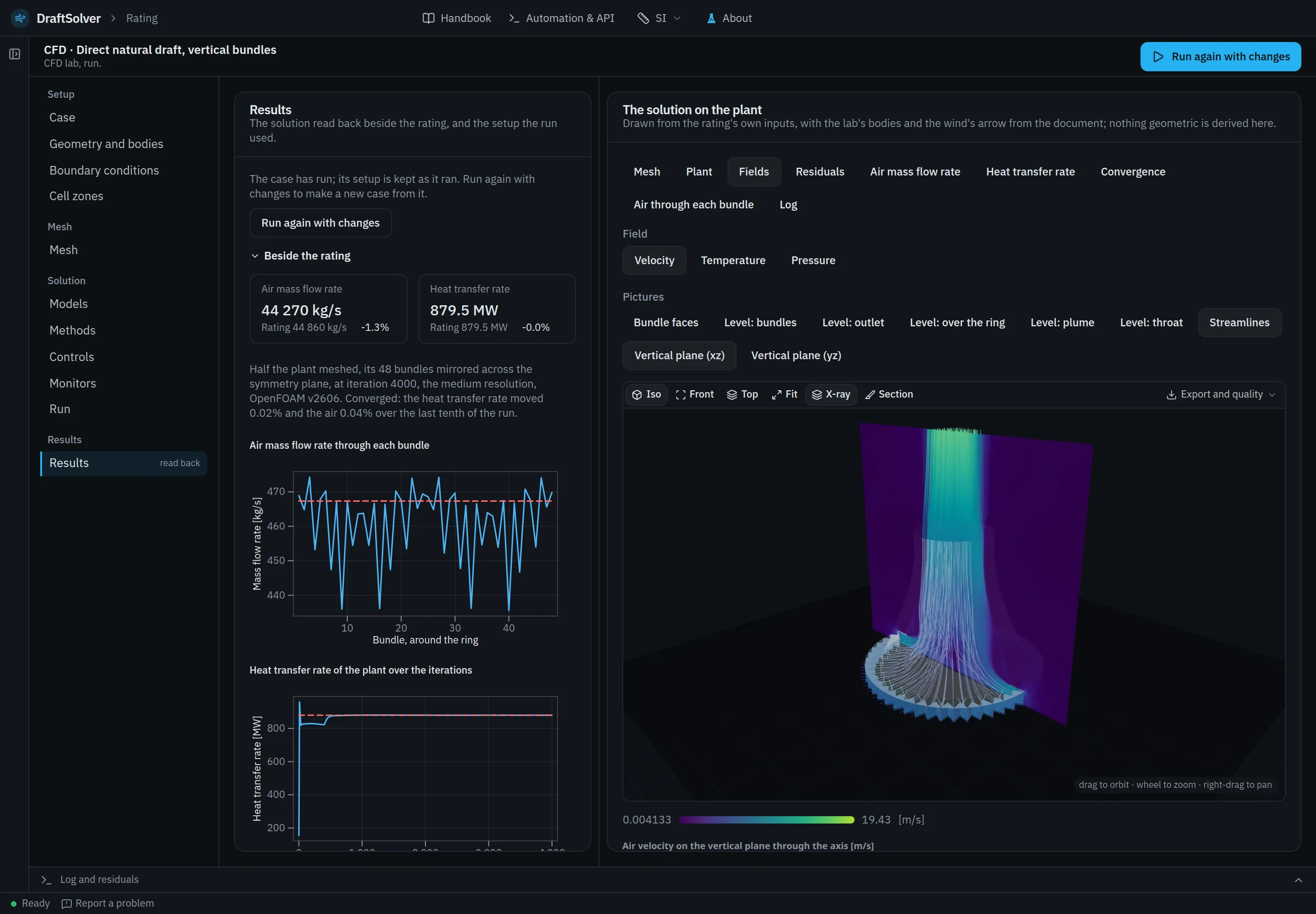
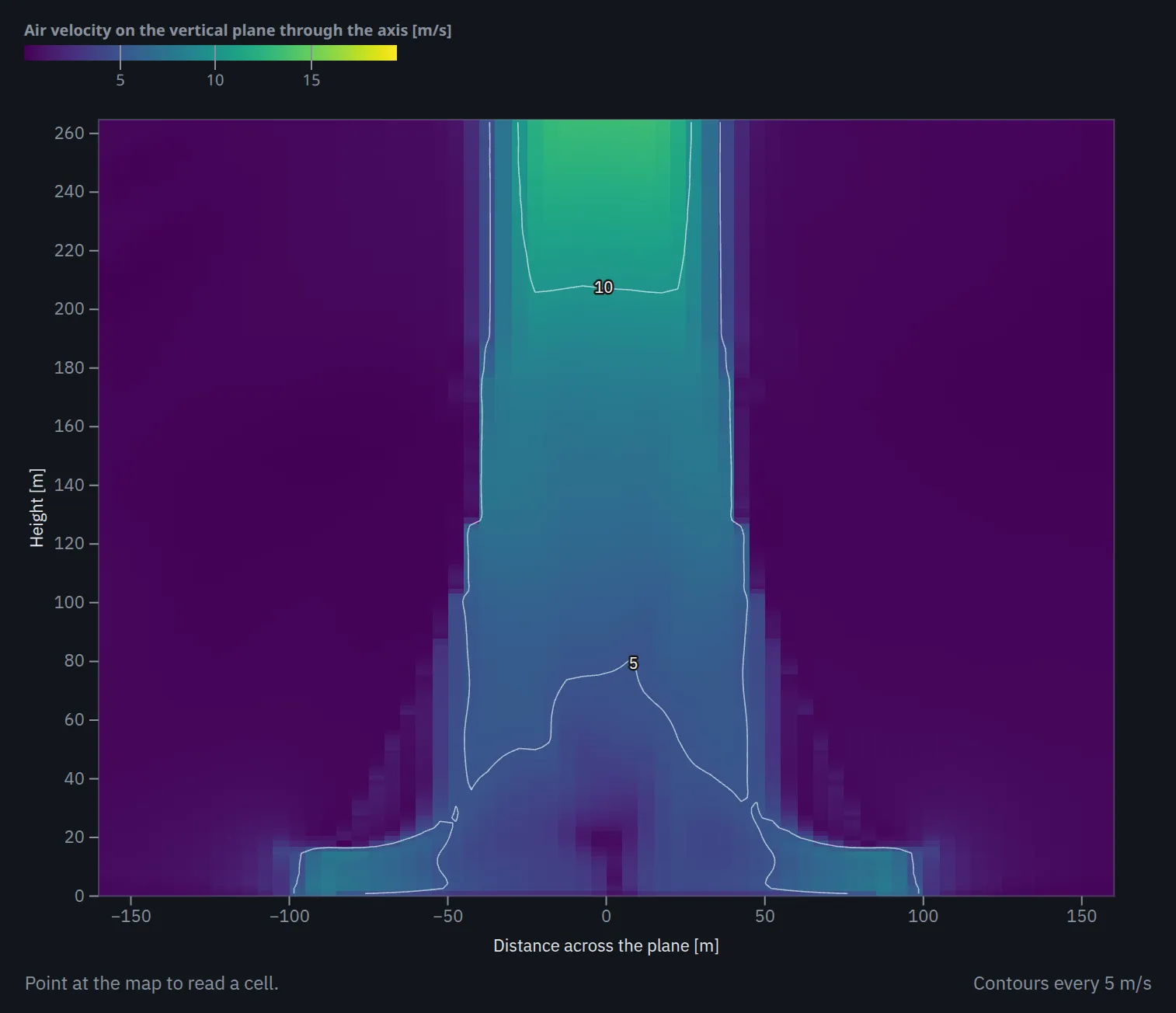
Any rating is ported to OpenFOAM as it stands: the plant's geometry, each bundle as porous zones on the rating's own tube law, each fan on its own curve, and the steam at its own temperature. The case is meshed and solved on Adiabat's compute service, with nothing to install, and the solution is read back beside the rating it came from, per fan, tube row and bundle.
- Run in CFD
- The rated plant ported to OpenFOAM as it is; the user chooses the mesh resolution, the turbulence model and the discretisation order, sees the mesh and its statistics before the solve, and reads the solution back beside the rating.
- Plans: Expert, Enterprise, every academic licence, the Trial, Pro with its add-on.
- CFD lab
- The whole case open in an outline from setup to mesh, solution and results: windbreak walls, bodies from STL, the wind's direction, the domain, refinement and layers, the turbulence, schemes, solvers and relaxation, monitors and probes.
- Plans: Expert and Enterprise, with every academic licence and the Trial.
- Co-simulation
- In the CFD lab, on every system: the CFD coupled to the rating's own model, in two forms. The steady co-simulation solves the CFD in blocks and, between them, rates every bundle's steam or fluid side again at the air the CFD gave it, splitting the flow from the header among the bundles until the split settles; it runs in a crosswind as it does in still air. The transient co-simulation is a fully transient simulation of the plant: the CFD runs time-accurately, window by window, beside the plant's own transient, as the steam or fluid conditions change.
- Plans: Enterprise, every academic licence and the Trial; an add-on to Expert.
One credit is one core-hour of CFD compute. Ratings, sweeps, designs, annual runs and transients use no credits.
A CFD solution and the rating are two models of one plant, and the comparison validates neither.
Every claim names what it was compared with
The validation catalogue holds 47 cases: 13 textbook worked examples, 2 measurements on operating plants, 13 measurements on controlled rigs and 19 comparisons with CFD, a co-simulation or another model. Kröger's worked examples are published calculations, not measurements. Each case states what was compared, against what, the agreement found and what that agreement shows.
| System | Compared with | Agreement |
|---|---|---|
Kröger publishes no worked example for an induced-draft A-frame, so this system has no textbook verification case of its own; its parts are verified as Examples 8.1.2 and 8.1.4. | Kröger's worked Example 8.1.4 | Air mass flow rate, heat transfer rate and fan power within 0.011%; every loss coefficient to five significant figures |
| Wang, Chi and Chang's (2000) coil database; the draft side, fan and platform on Kröger's Examples 8.1.1 and 8.1.2 | 88.6% of the coil database within 15%; no measured dry cooler is reproduced | |
| Kröger's worked Examples 8.1.1 and 8.1.2, and 9.3.1 and 9.3.2 under wind | Air mass flow rate within 0.10%, heat transfer rate and fan power within 0.04%, temperatures within 0.04 K; under wind within 1.5% and 0.5% | |
| The published design point of the reference tower | Heat transfer rate within 0.5%; air mass flow rate 3.5% above the published value | |
| Kröger's worked Example 7.3.1 | Heat transfer rate within 0.024%, air mass flow rate within 0.010%, both outlet temperatures within 0.005 K | |
Built, but not yet verified against a worked example. | An independent implementation of the same specification (another model, not a measurement) | Air mass flow rate within 0.7%, heat transfer rate within 0.2% |
The equations behind a result
Each result lists the equations that produced it. The Handbook in the app gives every equation's source, its coefficients, its fitted range and its stated accuracy, and a result outside a fitted range is reported as an extrapolation.
An uncertainty band on every rating
The band re-solves the plant with each correlation at the 95% bound of its stated accuracy and reports the interval each one contributes. It is included in every plan; Expert, Enterprise and Academic add a Monte Carlo over all of them at once.
Worked examples that check the build
The app ships complete cases with their expected results. When a loaded example is run, the results page reports the agreement of the build with the recorded and published values.
Published methods, cited
DraftSolver is an independent implementation of published methods: Kröger's one-dimensional methods for air-cooled heat exchangers and cooling towers, and the published literature on natural-draft dry cooling under crosswind and through start-up, including its author's two papers below. Both papers are open access, and each validation case cites its source.
W. Strydom, J. Pretorius and R. Laubscher
Co-simulation of transient start-up performance in natural draft direct dry cooling system under varying wind conditions
Applied Thermal Engineering 300 (2026) 131471. doi:10.1016/j.applthermaleng.2026.131471
W. Strydom, J. Pretorius and J. Hoffmann
Natural draft direct dry cooling system performance at various application scales under windless and windy conditions
Applied Thermal Engineering 248 (2024) 123181. doi:10.1016/j.applthermaleng.2024.123181
DraftSolver opens in 2027
Access is granted by application to owner's engineers and test agencies, consultancies, OEM and EPC bid engineers, data-centre engineers and universities. Each application is read by the engineer who builds the product.